Overdenture: Fixed Detachable Abutment
Page 1 | Page 2 | Page 3 | Page 4 | Page 5
Indirect Transfer Impression
 |
 |
 |
 |
 |
 |
 |
 |
 |
 |
 |
 |
 |
 |
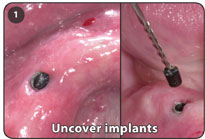
1. Uncover each implant using a small crestal incision and manually use the #110 reamer bur to facilitate the removal of the black healing plug.
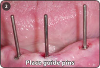
2. Place guide pins into the implants to determine the axial inclination of the implants.
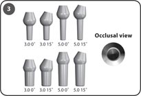
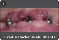
3. Select appropriate Fixed-Detachable (FD) abutment height that allows the hemispherical base to sit in the gingival sulcus.
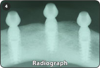
4. Radiograph of three implants with abutments for screw-retained restorations.
5. FD abutments have a threaded bore for screw retention and a 20˚ taper of the coronal portion.
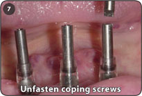
6. Place the metal or plastic transfer coping over the abutments and screw a 5.0mm or 10.0mm coping screw into the abutment to retain the plastic transfer coping for an open tray impression. Make an impression using an open tray impression technique.
7. Unfasten the coping screws through the open tray impression to allow for the pickup of the plastic transfer copings in the impression.
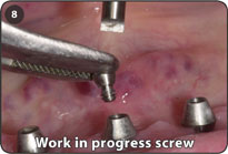
8. Screw a work in progress screw (260-100-021) to the abutment until the final prosthesis is ready for seating.
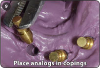
9. Place brass abutment analogs (260-100-006) into the plastic transfer copings within the impression.
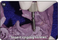
10. Insert coping screws into the plastic transfer coping to retain the brass abutment analog while pouring a stone model.
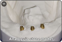
11. Three abutment analogs in a stone model.
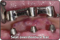
12. Seat the overdenture bar on the abutments to confirm passive seating.
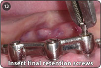
13. Insert final retention screws (260-100-020) to retain overdenture bar to abutments. Although slotted screws are depicted, hex retention screws are recommended.
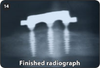
14. Radiograph of screw retained overdenture bar on three Bicon implants.
Notes: Bicon retention screws only have three threads, which is the maximum amount required when screwing identical materials together. A three threaded screw is sufficient, if the casting is passively seated on the abutments.
If the threads of the retention screws do not engage the abutments, the prosthesis is not passively seated.
The hex size is 1.25mm.
The Fixed-Detachable abutment can be used for crown restorations.
Measurement Guide: Fixed Detachable Abutment
The design of the Bicon abutment system is such that the hemispherical base of the abutment does not sit flush with the neck of the implant. By design, there is a space below the abutment post when the abutment is fully seated. When viewing this on a radiograph, it can be seen as a radiolucency. Please note that the post of any abutment may not be modified. Altering the abutment post in any manner or using a cementing medium will affect the frictional fit of the locking taper resulting in a potentially non-retentive abutment. The following diagram depicts the final seating of a fixed-detachable abutment as well as the method for measuring each abutment. |
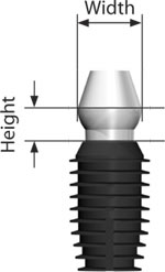 |
| The width of the abutment at its widest point is 4.0mm. The height of the fixed-detachable abutment is measured from the widest portion of the abutment to the top of the implant. The two available heights are 3.5mm or 5.0mm. This abutment has a 20˚ tapered head. |