Since 1985 » Simple. Predictable. Profitable.
Stealth Transitional Implants and Components
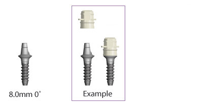
Stealth Transitional Implants
| Description | Angle | Dia. | Height | Part Number |
|---|---|---|---|---|
| 2.5 x 8.0 x 4.0mm 0˚ Stealth Transitional Implant | 0° | 2.5mm | 8.0mm | 260-425-108 |
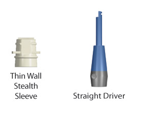
Stealth Transitional Implant Components
| Description | Dia. | Height | Part Number |
|---|---|---|---|
| 4.0mm Thin Wall Stealth Sleeve (4) | 4.0mm | 5.0mm | 260-250-204 |
| Straight Stealth Latch Driver | 260-101-905 |
Transitional Implant Considerations
- Drill a 2.0mm osteotomy to appropriate depth with Bicon’s 2.0mm pilot drill with external irrigation.
- Take care not to overheat the bone while drilling at ~1,100 RPM.
- Pilot bur is marked at 6.0mm, 8.0mm, 11.0mm and 14.0mm.*
- Be sure to drill to appropriate depth of intended implant to be placed or slightly beyond if the anatomy permits.
- Make note of the quality of bone.
- The O-Ring implants are available in 8.0mm and 12mm lengths and Stealth implants are available in 8.0mm length..
- Check angulation or trajectory of osteotomy with a paralleling pin.
- Remove appropriate transitional implant from packaging and insert apical end of implant into osteotomy.
- Assemble appropriate transitional implant driver to Bicon’s 400:1 handpiece or a comparable slow speed latch-type handpiece.
- Slowly screw implant into the prepared osteotomy.
*Some pilot burs may have markings only at 8.0mm, 11.0mm, and 14.0mm. Check burs before drilling. If there is any doubt about the markings on any drill or reamer, take a measurement prior to using the reamer. (See Pilot Drill Reference).